

How To Draw A Phasor Diagram For R-l-c Circuit
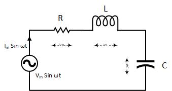
An RLC series circuit contains all the three passive electrical components, Resistor Capacitor, and Inductor in series across an Air-conditioning source. Equally in that location is simply one path for current in a series combination, the electric current in all these components is the same in magnitude and phase.
We know that voltage and electric current are in phase in a pure resistor while current leads in a purely capacitive excursion and the case of a purely inductive circuit, electric current lags. Then, what nigh the voltage across each component, if their behavior is so different?
To answer the question, we volition showtime detect the impedance of the series RLC excursion.
Before going further, I would like to have the electric current phasor equally a reference. Considering the current is the same in all the components of the RLC series excursion. And then, information technology is more than robust to compare different quantities to the same electric current.
Impedance Triangle in RLC serial excursion:
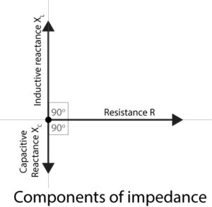
The full impedance of an RLC series circuit can exist plant using an impedance triangle. Offset of all, nosotros have to consider the resistance and reactance of each component and so put them into the impedance triangle to detect the total impedance of the RLC circuit.
Resistance: $R∠0^o$
Inductor Reactance: $X_L=ωL∠90^{o}$
Capacitor Reactance: $X_{ C }=\frac{one}{ωC∠-90^{ o }}$
By observing the to a higher place equations, the capacitive reactance and anterior reactance are opposite in management of each other.
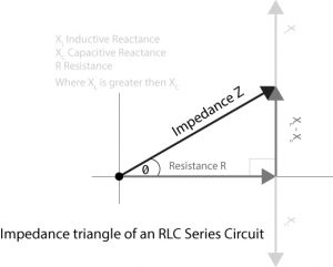
In the impedance triangle, resistance, capacitive reactance, and inductive reactance phasors volition be added to each other using parallelogram law or head and tail rule. The final impedance tin be leading or lagging depending upon the departure betwixt the capacitive and inductive reactance magnitude. If the capacitive reactance is larger than inductive reactance, impedance phasor will brand a negative angle with the horizontal line or vice versa.
In the above impedance triangle, I have causeless inductive reactance is larger and it is making a positive bending with resistance phasor. The total impedance of the RLC circuit is represented with the following formula
$Z=\sqrt{ (R^{ 2 }+(X_{ L }-X_{ c })^{ ii }) }$
Electric current in RLC serial circuit:
According to the Ohms Police force in Air conditioning excursion, the current of an AC circuit can be found using the following formula
$I=\frac {V}{ Z}$
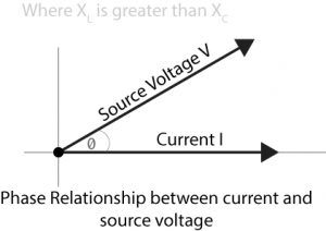
The phase difference betwixt the current and voltage will depend upon the impedance. If the impedance is more inductive, the current volition lag and if the impedance is more capacitive, then the current will be leading.
Equally I have assumed inductive reactance larger than capacitive, so the current, in this instance, will lag behind the source voltage.
The voltage across each component in the RLC serial circuit :
Applying KVL at the RLC circuit, we will get the following equation
$V_s=V_R+V_L+V_C$
Using the bones current and voltage relationship in resistor, inductor, and capacitor current flow, the above equation tin be modified as follow
$V_s=IR+\frac{50 di}{dt}+\frac{i}{C}\int {idt}$
The voltage across each circuit chemical element can exist found using the post-obit formula
Resistor voltage driblet: $V_{ R }=IR$
Inductor voltage drop: $V_{ L}=IωL∠-90^{ o }$
Capacitor voltage drop: $ V_{ C }=\frac{I}{ωC}∠90^{ o }$
The voltage drop in the resistor will exist in stage with current, in the example of the capacitor the current will leads to voltage drop, and for the inductor, the current of the inductor will be lag from the voltage driblet in the inductor. The same affair is represented with the phasor diagram.
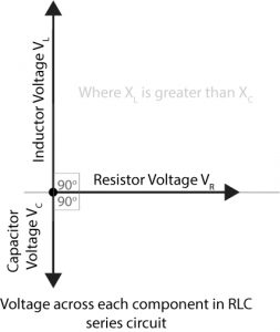
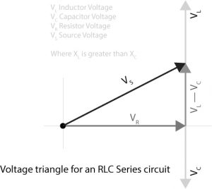
The above vectors from the higher up diagram can exist added vectorially which volition get u.s.a. the voltage triangle. The vertical component of the triangle shows the voltage drop across reactance (inductive and capacitive) and the horizontal component shows a drop beyond the resistance.
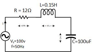
Example with the solution:
For the given circuit diagram calculate the RLC serial excursion impedance, current, voltage beyond each component, and power gene. Likewise describe the phasor diagram of current and voltage, impedance triangle, and voltage triangle.
First of all, let me summate the total impedance with the following formula
Resistance: $R=12\Omega$
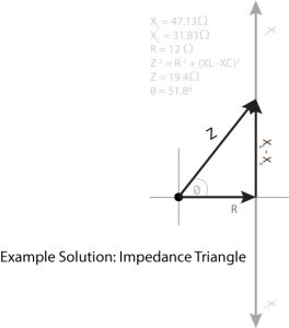
Anterior Reactance: $X_{ L }=ωL=two\pi fL=2×\pi×50×0.15=47.one\Omega$
Capacitive Reactance: $X_C=\frac{i}{ωC}=\frac{1}{2\pi fC}=\frac{1}{2×\pi×fifty×100×10^{-6} }=31.83\Omega$
Now the total impedance will be
$Z=\sqrt{R^{ 2 }+(X_{ Fifty }-X_{ C })^{ 2 }}\ Z=\sqrt{12^{ 2 }+(47.xiii-31.83)^{ ii }}$
$Z=\sqrt{144+234}\ Z=nineteen.4\Omega$
Where the current is
$I=\frac{V}{Z}=\frac{100}{19.4}=5.14amps$
The voltage across each component in the RLC excursion
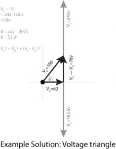
The voltage beyond resistor: $V_{ R }=IR=5.14×12=61.7v$
Voltage across capacitor: $V_{ C }=IX_{ C }=five.xiv×31.eight=163.5v$
The voltage across inductor: $V_{ 50 }=IX_{ Fifty }=5.fourteen×47.thirteen=242.2v$
Observing the in a higher place individual voltages, their scaler summation can get us a larger voltage than the source voltage. Take a wait at the following vector diagram.
Where the power factor of the circuit is
$cos { \theta } =\frac{R}{Z}=\frac{12}{19.4}=0.619\quad lagging$
Every bit from the above calculation, we have observed that inductive reactance is larger than capacitive, then the power factor is considered lagging.
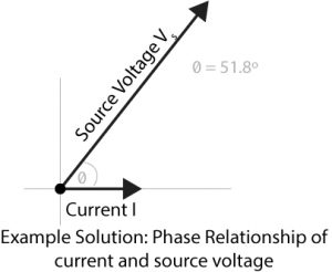
$cos{\theta}=0.619$
$\theta=cos^{-1}{0.619}=51.8^{ o }\quad lagging$
RLC Serial excursion figurer :
RLC circuit figurer calculates the inductive impedance, capacitive impedance, total impedance, and total current. It also calculates the voltage across resistor, inductor, and capacitor and the phase angle between the current and voltage.
Determination:
- If resistor, inductor, and capacitor are continued in a serial Ac circuit, the circuit will exist chosen an RLC series circuit.
- The phase deviation between voltage and current is adjusted past the difference between capacitive and inductive reactance.
- In the impedance and voltage triangle, quantities are added vectorially.
- If anterior reactance is larger, the circuit will respond as if it is an inductive circuit and vice versa.

Source: https://electric-shocks.com/rlc-series-circuit-phasor-diagram-with-solved-problem/
Posted by: hickstherinchis.blogspot.com
0 Response to "How To Draw A Phasor Diagram For R-l-c Circuit"
Post a Comment